

Next: 4.3 USO frequency characteristics
Up: 4. DWE Instrumentation: Ultrastable
Previous: 4.1 Transmitter and Receiver
The DWE USOs are designed to withstand the Cassini/Huygens
launch and cruise phase (ten years in the event of a
1999 back-up launch),
as well as the Huygens atmospheric entry and descent on Titan.
The TUSO on the Huygens Probe is exposed to higher mechanical loads
during the Huygens mission than the RUSO on the Cassini Orbiter.
The most critical factor for the TUSO, a major driver in the selection
of an ultrastable oscillator based on rubidium technology,
is the peak deceleration of
up to 16.1 g during the Huygens entry phase.
It could not be guaranteed that the required frequency stability of
 /
/ < 2·10E-10
(
 = nominal output frequency) could be met after the
probe entry into Titan's atmosphere with a state-of-the-art
quartz oscillator.
The high mechanical load during entry might cause a deformation of
the internal quartz fastening system in combination with an
unpredictable frequency offset and an unknown frequency relaxation time.
A similar problem with continuously varying mechanical stresses on
the quartz box was foreseen in the subsequent pressure variation
from 0 to 1.5 bar during the Huygens descent phase.
These adverse effects can be averted with a rubidium oscillator, for
which the frequency source is also a quartz, because the nominal
output frequency is locked to the very stable
frequency of the rubidium ground-state hyperfine transition.
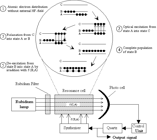
The basic principle of a rubidium oscillator (see Fig. 7)
is to utilize the two ground-state hyperfine levels A and B and a
much higher optical level C of rubidium atoms to produce an error
signal for the control circuit of a voltage-controlled quartz
oscillator VCXO.
Infrared light from a rubidium lamp is filtered and passes through
the heated rubidium resonance cell with a frequency
 =
=  -
-
 , exciting transitions to state C
of the rubidium gas.
Atoms in level C drop back after a very short time either to
state A or, with less probability, to state B.
Because atoms in state A are continuously re-excited to C, the
population of level B steadily increases ("optical pumping").
When state A is depopulated, a maximum photocurrent is produced in the
photocell since the light is no longer attenuated by
excitation processes from level A to C.
The HF-signal of the syntheziser, which is upconverted from
the quartz output signal, also irradiates the rubidium resonance cell.
The syntheziser is calibrated to generate the exact resonance
frequency
 =
=  -
-

 6.835 GHz if the
quartz has its nominal output frequency.
At this frequency atoms in level B de-excite to state A thereby
inducing a minimum photocurrent, because the rubidium vapor is no
longer transparent to the frequency
 .
Deviations from the minimum current condition are produced by
deviations in the nominal VCXO output frequency.
The current dip, however, is very small (0.1% of the total
photocurrent) and not suitable for a DC detection.
To circumvent this shortcoming, the synthesizer frequency is
modulated at an audio frequency
  Hz.
The similarly modulated photocurrent can now be AC detected by
synchronous current demodulation.
There is a positive correlation between the sign of the current
error signal (positive or negative) and the offset from the nominal
quartz output frequency.
This error signal is used to lock the nominal quartz signal to
the rubidium resonance frequency by varying the quartz control voltage.

Figure 7: Operation principle of a rubidium
oscillator.
The USO consists of the Physics Package (rubidium resonance
cell and lamp) and several printed circuit boards, which contain
discrete electronic elements as well as integrated circuits.
The USO electronics and the Physics Package are integrated into
an aluminium box, which is constructed as a Faraday cage to avoid
electromagnetic contamination of the USO environment.
The USO box is attached to the experiment platform via
4 mounting studs, thereby providing a thin air buffer for better
insulation from the mounting platform.
This reduces the USO conductive heat loss, saving power
that would otherwise be needed for heating.
The box surface is plated with nickel and coated with Chemglaze Z 306.
The total mass of the USO is  1.9 kg.
The electronics and physics package is surrounded by
  -metal
shielding to minimize the effects of changes in the
external magnetic fields that range from more than 1·10E4 nT on
Earth to essentially zero at Titan.
Variations in the ambient magnetic field induce a change in the
Rb hyperfine resonance frequency and thus a frequency shift in
the USO output signal.
Radiation sensitive USO components such as transistors
and analogue IC's are radiation hardened up to 10 krad.
While the maximum radiation dose for the probe TUSO is
  5 krad, the RUSO on the orbiter will be exposed to about 18 krad in
the event of a 1999 launch.
In order to provide additional radiation protection for the RUSO,
the critical components of both USO units are shielded with
tantalum caps (thickness
  1 mm).
Radiation shielding contributes about 10% to the total
USO mass budget.
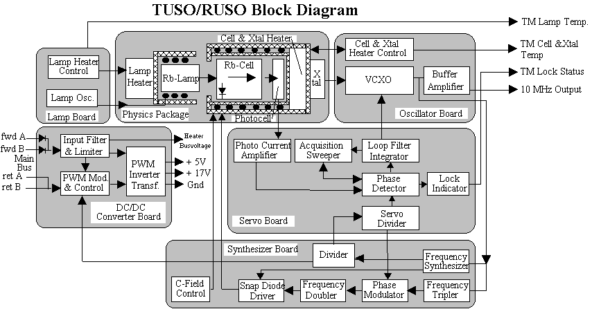
A block diagram of the USO unit is shown in
Fig. 8.
The external supply voltage of 28 V (TUSO), or 30 V (RUSO),
is transformed down to 5 V and 17 V by the DC/DC converter.
The converter control signal is provided by the syntheziser,
synchronized to the quartz output signal.
The VCXO quartz, located on the Oscillator Board,
provides the 10 MHz output through a buffer amplifier.
The same signal is upconverted by the Syntheziser to the rubidium
resonance frequency.
The photocurrent of the Physics Package is routed to the Servo Board,
which generates the error signal for the voltage control of
the VCXO.
The heater control of the rubidium lamp within the Physics Package
is located on a separate Lamp Board.
Three analogue sensors monitor the temperatures of the rubidium lamp,
rubidium cell and VCXO, respectively.
A bi-level lock indicator flips from "0" to "1" whenever the
quartz output signal is in lock with the rubidium resonance frequency.
The temperatures and lock indicator signal are part of the
Huygens HK data.
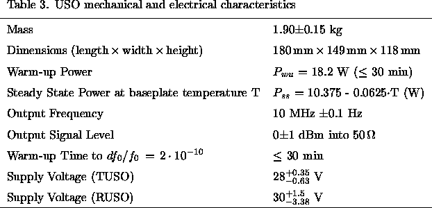
Table 3 summarizes the USO
mechanical and electrical characteristics.

Figure 8: USO Block Diagram.


Next: 4.3 USO frequency characteristics
Up: 4. DWE Instrumentation: Ultrastable
Previous: 4.1 Transmitter and Receiver
DWE Homepage - For further information contact r.dutta-roy@freenet.de
 /
/ < 2·10E-10
(
 = nominal output frequency) could be met after the
probe entry into Titan's atmosphere with a state-of-the-art
quartz oscillator.
The high mechanical load during entry might cause a deformation of
the internal quartz fastening system in combination with an
unpredictable frequency offset and an unknown frequency relaxation time.
A similar problem with continuously varying mechanical stresses on
the quartz box was foreseen in the subsequent pressure variation
from 0 to 1.5 bar during the Huygens descent phase.
These adverse effects can be averted with a rubidium oscillator, for
which the frequency source is also a quartz, because the nominal
output frequency is locked to the very stable
frequency of the rubidium ground-state hyperfine transition.


 =
=  -
-
 , exciting transitions to state C
of the rubidium gas.
Atoms in level C drop back after a very short time either to
state A or, with less probability, to state B.
Because atoms in state A are continuously re-excited to C, the
population of level B steadily increases ("optical pumping").
When state A is depopulated, a maximum photocurrent is produced in the
photocell since the light is no longer attenuated by
excitation processes from level A to C.
The HF-signal of the syntheziser, which is upconverted from
the quartz output signal, also irradiates the rubidium resonance cell.
The syntheziser is calibrated to generate the exact resonance
frequency
 =
=  -
-

 6.835 GHz if the
quartz has its nominal output frequency.
At this frequency atoms in level B de-excite to state A thereby
inducing a minimum photocurrent, because the rubidium vapor is no
longer transparent to the frequency
 .
Deviations from the minimum current condition are produced by
deviations in the nominal VCXO output frequency.
The current dip, however, is very small (0.1% of the total
photocurrent) and not suitable for a DC detection.
To circumvent this shortcoming, the synthesizer frequency is
modulated at an audio frequency
  Hz.
The similarly modulated photocurrent can now be AC detected by
synchronous current demodulation.
There is a positive correlation between the sign of the current
error signal (positive or negative) and the offset from the nominal
quartz output frequency.
This error signal is used to lock the nominal quartz signal to
the rubidium resonance frequency by varying the quartz control voltage.

 1.9 kg.
The electronics and physics package is surrounded by
  -metal
shielding to minimize the effects of changes in the
external magnetic fields that range from more than 1·10E4 nT on
Earth to essentially zero at Titan.
Variations in the ambient magnetic field induce a change in the
Rb hyperfine resonance frequency and thus a frequency shift in
the USO output signal.
Radiation sensitive USO components such as transistors
and analogue IC's are radiation hardened up to 10 krad.
While the maximum radiation dose for the probe TUSO is
  5 krad, the RUSO on the orbiter will be exposed to about 18 krad in
the event of a 1999 launch.
In order to provide additional radiation protection for the RUSO,
the critical components of both USO units are shielded with
tantalum caps (thickness
  1 mm).
Radiation shielding contributes about 10% to the total
USO mass budget.

